Studying moving bodies effects on flows
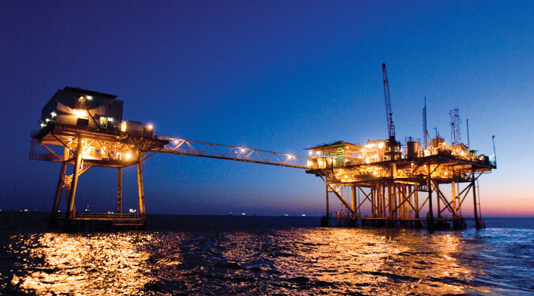
Moving bodies immersed in fluid flows are found in a wide range of contexts, with Oil & Gas being a particularly relevant one.
This project focuses on the "Piping and Valves" equipment category, a specific field often encountered in the Energy and Oil & Gas sectors. In particular, it analyzes the interaction occurring between a Variable Orifice Valve plate when it is operated while immersed in gas flowing inside the valve. This plate mainly regulates the pressure drop across the valve and is one of the fundamental elements for process control in typical industrial plants. When operated, it induces time-dependent variations in the thermodynamics of the fluid flow, depending on many factors such as plate shape and operation dynamics (velocity, kinematic law, etc.).
PhyMo implements modern, state-of-the-art technologies that enable the study of moving objects interacting with fluid flows. These capabilities make it possible to investigate time-dependent flow behavior from both qualitative and quantitative points of view, visualizing variable evolution as well as plotting pressure drop, or forces and moments, over time.
That is precisely what was done in this study. Details are presented in the following sections.
Analysis details
Given the presence of moving bodies, which induce instantaneous changes in flow variables, this analysis is inherently time-dependent. The CAD model must be properly prepared by separating moving objects from fixed ones. The computational grid is then generated accordingly, differentiating the two. PhyMo offers advanced meshing capabilities that make it possible to handle such complex contexts intuitively while maintaining state-of-the-art accuracy.
To fully define the problem, specific values must be assigned to the variables at the boundaries of the domain: prescribe flow velocity at the domain inlet, set a fixed outlet pressure, and enforce a no-slip (adherence) condition on solid walls. For moving bodies, one must also define the "law of motion" for the moving part, in this case, a simple rotation around an axis passing through a user-specified point at a fixed rotational speed was used.
With a correctly and completely set problem, the software can start the calculation. Since this is a time-dependent simulation, it continues until it reaches the user-defined final time, in this case, 5 seconds. Once completed, the result file can be post-processed to gain relevant insights into system behavior.
Results visualization
When visualizing simulation results, two broad categories are typically encountered: qualitative and quantitative. The first category provides a high-level, general overview of what is happening inside the computational domain. This is especially useful for building a first understanding of the underlying phenomena, such as identifying high-speed zones or turbulence-enhancing elements. The second category is invaluable for precisely quantifying variables of interest. These numerical values can be used to drive product design and optimization, estimate performance improvements, or predict product failure.
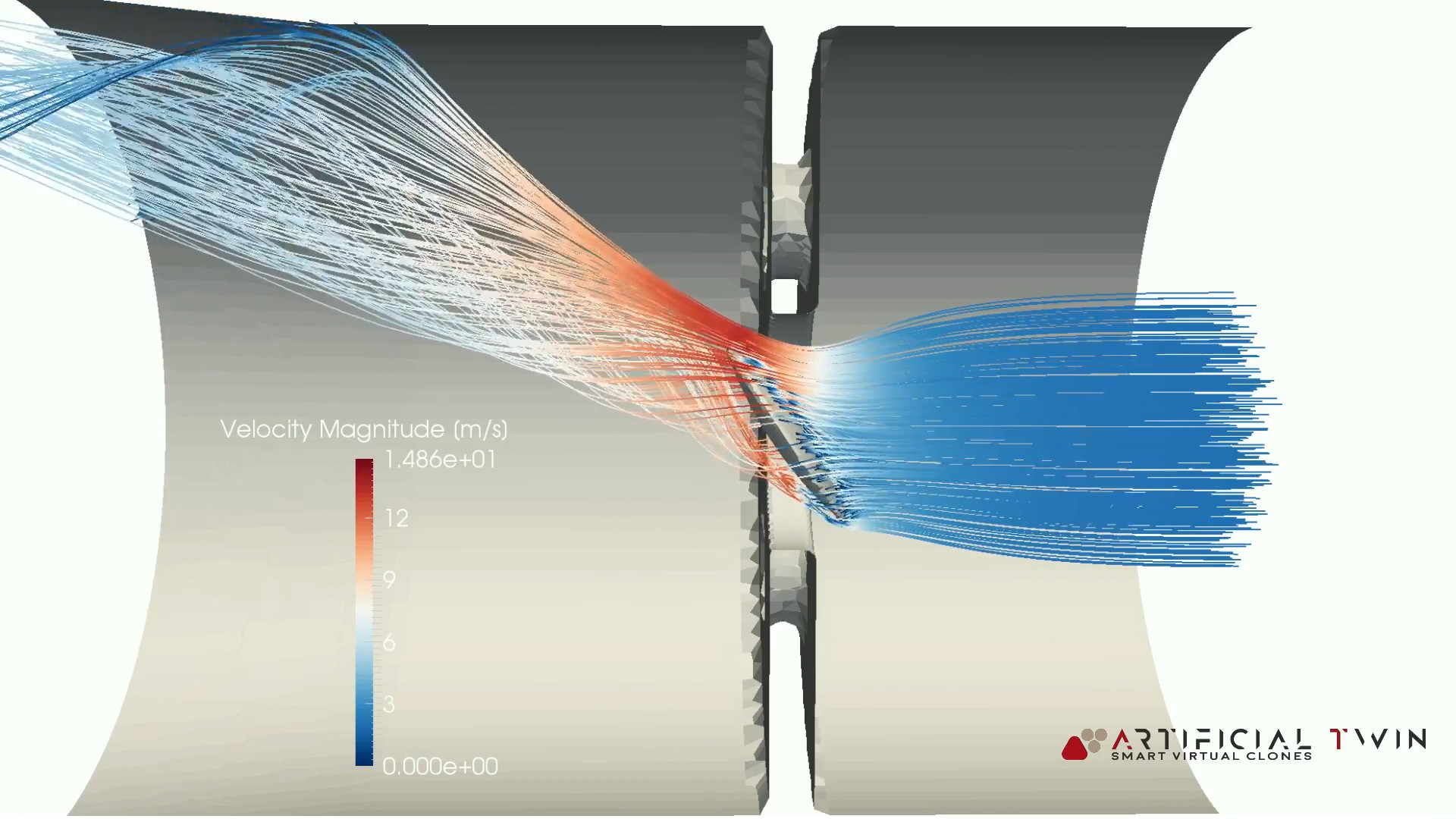
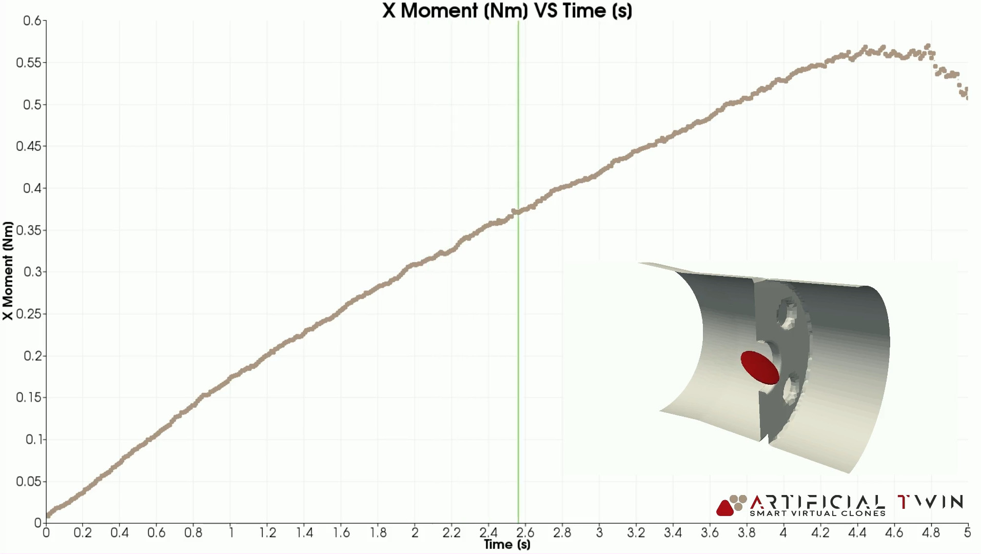
As usual, both qualitative and quantitative results were included in the final report. The image above, for instance, shows the flow lines at a specific time step, while the one on the left plots the X-moment acting on the valve plate over time.
A comprehensive overview of the results is presented in the video below. It brings together several different visualization techniques: velocity field contours, pressure contours, streamlines, surface pressure contours, pressure evolution along the valve’s longitudinal axis, and the X-moment on the valve plate over time.
Same approach, large number of potential applications
Moving parts are frequently encountered in industrial contexts: from valves to fans, from mixing tanks to internal duct flaps, these systems all feature components that change position during operation to achieve a particular goal, such as controlled modulation of pressure drop or kinetic energy transfer.
The approach presented in this study can be easily extended to many adjacent cases, as the underlying physics remains the same. PhyMo thus makes it possible to simulate all scenarios in which an element moves within the computational domain, enabling detailed investigation of its influence on flow behavior, timestep by timestep.