Certified pressure vessel design through simulation
Pressure vessel design is a classical topic in mechanical engineering, studied extensively and relevant across many industries. While the theoretical background, particularly for linear elastic materials, is well established, strict compliance with regulations is always required due to the potential hazards involved.
This is especially critical when a component requires certification of conformity. Inspectors must ensure that simulation tools are used properly, following approved methodologies to guarantee safety and reliability.
PhyMo played a key role in this study, supporting structural verification of a pressure vessel component through Finite Element Analysis (FEA). As part of a broader certification process, PhyMo ensured accurate and trustworthy results, making it an essential tool for structural assessments of this kind.

ASME regulations on Design by Analysis
The ASME Boiler and Pressure Vessel Code Section VIII, Division 2 - Alternative Rules provides procedures for pressure vessel design using simulation. It defines simulation software requirements and lays out detailed verification methodologies.
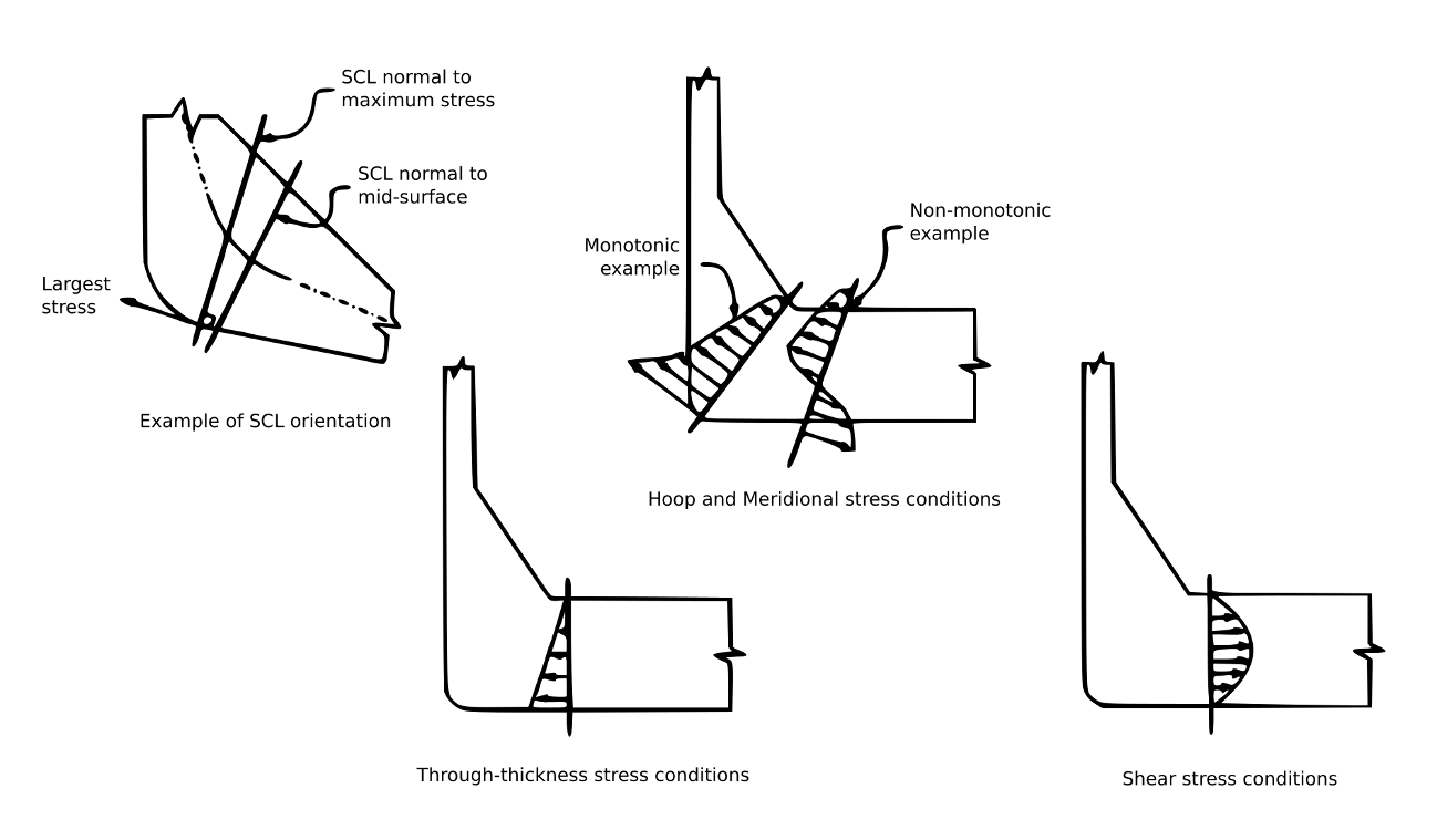
These procedures can be technically demanding, especially for inexperienced FEA users. One example is the use of a Stress Classification Line (SCL), shown in the adjacent image. It is used to classify stress components (e.g., primary, secondary) along a specific path in the geometry.
Accurate stress calculations are essential, as components are subject to complex mechanical loads and boundary conditions. A reliable FEA solver is critical to compute stress distribution with the necessary precision for regulatory compliance.
Stress calculation using virtual simulation
A high-accuracy FEA solver was used to simulate the pressure vessel component. The process began with CAD modeling and simplification, removing irrelevant details and splitting faces where loads and constraints would be applied.
The next step involved mesh generation. In this case, second-order tetrahedral elements were used for better precision. After meshing, boundary conditions were applied: a surface pressure to simulate internal pressure, and displacement constraints at rivet locations. All other surfaces were left unconstrained.
With this setup, the simulation was run and results were post-processed for stress and deformation analysis.
Testing virtual models in early design phases
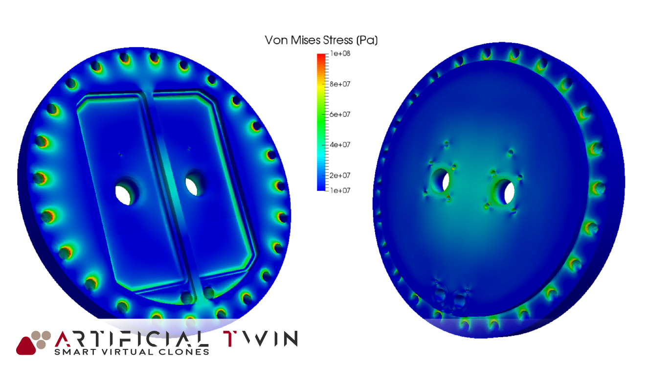
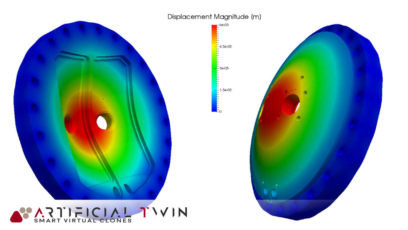
Once the simulation is complete, results can be analyzed to assess variables of interest and ensure compliance with standards. Two key outputs are shown here: Von Mises stress and total displacement.
The Von Mises stress plot highlights critical regions prone to structural failure. The deformation view, amplified for clarity, helps identify maximum displacement and overall behavior under load.
This case study demonstrates the many advantages of virtual testing. With modern FEA tools, simulation has become a certified and reliable method for structural design, providing fast, accurate insight even in safety-critical applications.