Scaling software potential super-fast
This success story describes how CoGe, our advanced technology for Computational Geometry, enabled an Italian company providing advanced Computational Fluid Dynamics simulation services to rapidly scale their capabilities with top-class reliability and robustness.
CAD models are the primary source of geometrical information in Mechanical Engineering. For software in this field, supporting as many input file formats as possible guarantees a strategic market advantage. Leveraging our production-ready tool, which can ingest and discretize NURBS files (such as STEP, IGES, BREP, ACIS, Parasolid) as well as common polygonal mesh formats (like STL or OBJ), provides a highly valuable feature.
Additionally, our professionals’ deep expertise allows them to design, develop, and deliver plug-and-play solutions tailored to the customer’s specific needs, constraints, and interfaces, adapting state-of-the-art algorithms and methods as required.
CAD models and NURBS files
CAD models are created by combining mathematical descriptions of shapes. By assembling basic elements with CAD software, it is possible to generate 3D objects with the desired level of complexity and accuracy.
These models are a fundamental part of modern engineering, serving as essential building blocks in processes ranging from design and virtual testing to 3D printing and prototyping.
Once created with specialized applications, CAD models are used as input for any activity that requires a precise geometrical description of the object. A common way to provide this is through NURBS files, standard formats that describe shapes using mathematical functions, ensuring no loss of accuracy or need for discretization compared to the original model.
CoGe natively supports many NURBS-based CAD files, including STEP, IGES, BREP, ACIS, Parasolid, and others. This enables both exact modifications (such as Boolean operations) and flexible discretization at any desired level of refinement.
Simulation software and its objects
In this project, CoGe played a major role in scaling simulation software capabilities. PM2 Engineering is an Italian company specializing in advanced Computational Fluid Dynamics services. While they sometimes use third-party tools, they also develop and maintain their own CFD simulation software, which includes grid generation, solution algorithms, and post-processing. Their code implements the immersed boundary method with anisotropic Cartesian grids and coupled density-based solvers.
Previously, their software could import various polygonal mesh formats, such as STL and OBJ, as input geometries for CFD simulations. They wanted to add support for NURBS files, enabling compatibility with all major CAD file types as inputs for their platform.
These geometry files are fundamental for simulation software, as they define the computational domain, set boundaries, and describe internal shapes and elements. For example, they are used to specify the domain enclosing an urban area for environmental simulations, or to define the external aerodynamic profile of a vehicle for performance testing.
Flawless integration delivered
Relying on CoGe technology, PM2 Engineering received a state-of-the-art, reliable, and optimized solution, fully ready for integration into their production environment. The expertise of Artificial Twin in advanced software development ensured seamless custom integration, with the source code already adapted to the specific interfaces of their main application.
This approach demonstrates our commitment to meeting every customer need, leveraging our extensive experience to deliver a market-ready solution rapidly. As in this project, we are also open to providing the source code, empowering customers to independently maintain and expand the solution as their application evolves.
Throughout development, we adopt a modern agile methodology. Incremental and continuous delivery, supported by rigorous unit and regression testing, ensures complete customer satisfaction and alignment with project goals at every stage. Close collaboration and communication are always prioritized and, as in this case, have been key to quickly achieving the final solution.
CoGe in action
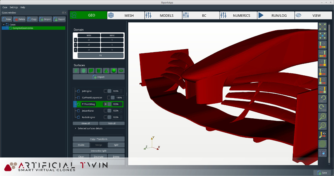
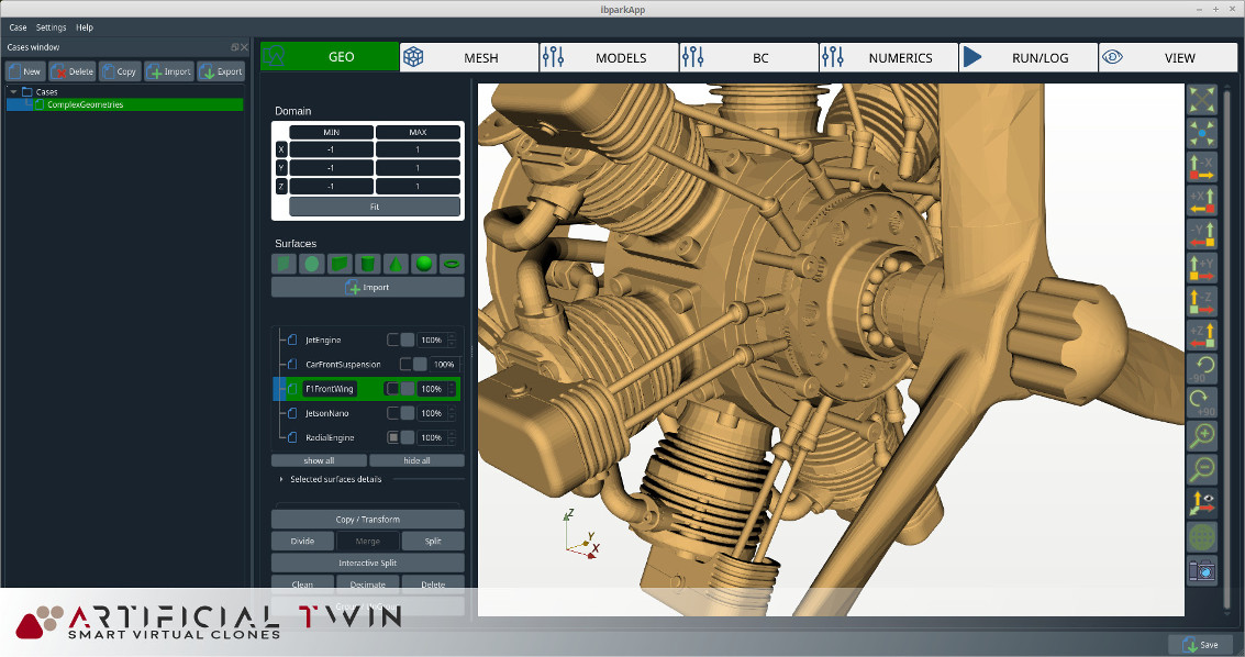
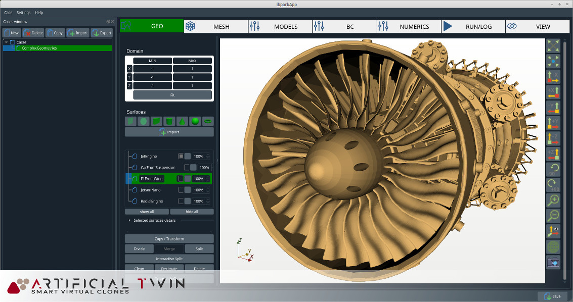
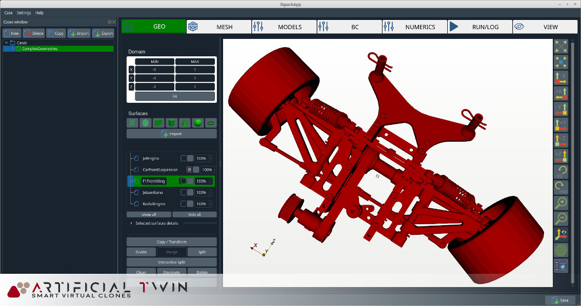
The video on the right shows a number of very detailed and "heavy" CAD models being successfully opened inside PM2 Engineering's software application after **CoGe** integration.
Screenshots on this page display examples of advanced CAD models where the number of polygons generated by discretizing the original NURBS file reaches several million. The accuracy of this discretization is controlled by two parameters with sensible default values for non-expert users, but they can also be customized for linear and angular resolution as needed.
CAD files can be extremely demanding to process. For this reason, having an optimal discretization tool is essential for a flawless user experience. Even with the most complex models, **CoGe** can read and discretize geometries and populate custom data structures in less than 60 seconds on a standard CPU.
Our experience in the field also enables us to identify optimization opportunities for our customers, providing a high-value service that we believe fosters success for both parties.